How To Make A Sliding Seat Rowing Rig
Many people enjoy an aerobic rowing experience, try it with little expense
| Click for printable version (discludes header and navigation bar; opens in new window) | ||
| EDITORS NOTE: This sliding seat material comes from reprinted materials originally authored 1947. As such the quality of the illustrations is quite limited and the information is largely dated. Platt suggests a few modifications to the design that will not be reflected in most of the illustrations that can be summarized as follows: The length of the machine should be 6" longer than the original; people got taller. The length of the track rails was 26" now 32" and the base is 6" longer - now 55" This material is supplied purely as a conceptual guide. The printed sliding seat pamphlet is five pages long and includes additional information about outriggers and oars. This tutorial has been limited to just the sliding seat with links provided to separate pages for the outrigger and oars to make page viewing faster for people with slower internet connections. | ||
| View outrigger tutorial | View oar tutorial | ||
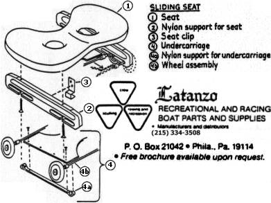
This sliding seat design for a canoe is based on material taken from a 1947 article published by the First Aid and Water Safety Service of the Red Cross by Waldemar Van Brunt Claussen. It is a simple, inexpensive approach for the entry level rower to utilize one boat for a double function. This kind of a varsatile rig is, of course, not as fast as a true rowing shell; however, it will provide the equivalent exercise with a lot more forgiving equipment at a far lower cost.. The seat frame is made from spruce or pine with a Few strips of oak for rails. In lieu of the seat shown, I used a Latanzo rolling seat at about $60.00. This required fabricating a couple of angle brackets for hold downs.
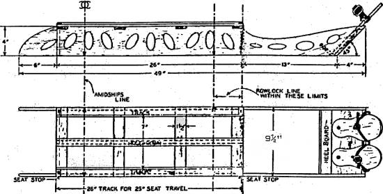
The drawing shows a sliding seat unit that can be readily placed in a boat and outriggers that can easily be clamped to the gunwales with wing bolts. The lightweight oars are made from dimension lumber and plywood. The
seat frame, a rectangular affair 49 (55 suggested) inches long,
9 1/2 inches wide, and 4 inches high, can be made from the planking
of a light packing case. If you wish to keep the outfit really
light cut the lightening holes indicated. Any of the modern plastic
resin glues make for excellent assembly, although screws may be
used if desired. The seat, the foot-plates, usually called boots,
and the tracks may be purchased from:
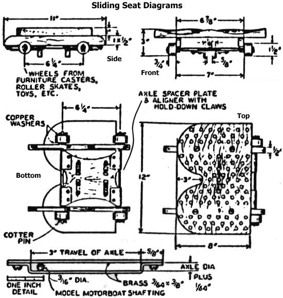
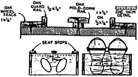
A couple of wood cleats 8 1/2" long are Fitted between the side rails and Fastened to the floor boards of the boat to position the SEAT unit. Use 3/16" line lanyards from screw eyes in the rails and tied under a convenient rib. The oak tracks, guard rails, and hold-down present a little work in sawing end planing if no power tools are available, because these parts should be true and smooth. The commercial seat hold down arrangement hooks under the edges of the slide rails and makes the center hold-down bar unnecessary. The sliding, or rolling, seat portion is interesting to make. The part you sit on maybe flat, if a pad of some kind is used with it; but a more shipshape job cells for gouging this 12" by 8" by 1” piece of soft wood into a typical saddle-seat form. The gouging job can be done with en ordinary straight 3/4-inch gouge chisel Followed by rubbing with coarse end fine sandpaper on an oval-shaped cork rubbing block (or a wooden' block faced with felt or foam rubber). Lightening holes again are drilled and it might even facilitate the gouging to drill them first. Wheels are obtained by dismantling the casters from some old article of Furniture. Even the wheels from roller skates or some inexpensive toy may be adapted to the purpose. Round iron rod may be used for the axle; but for a durable rig for adult use, a mild steel axle is better. The axle may be bought in 3/16-inch diameter stock and 12-inch lengths, at model shops where it is sold as shafting for model motorboat construction. Simplest manner of keeping the wheels on is to use washers and cotter pins after cutting the rod to proper length and carefully drilling the ends. The axle-keepers and bearings are designed to provide 3-inch travel for the axle; these may be iron or brass. They may be attached with offset bends in the keeper, or the bends may be eliminated end washers or spacers slightly thicker than the diameter of the axle used. The spacer plate, which keeps the axles in parallel alignment, should be about as thick as the diameter of the axle. The plate is held to the axle by light brass or tin clips bent around the axle and riveted to the plate. The "fingers," or "claws," to engage the hold-down rai1, and the rail itself are not strictly necessary for use of the equipment when rowing, but they are a worthwhile convenience because they keep the seat permanently attached when the frame is lifted into or out of the canoe. One or two pairs of claws may be used; these are readily bent and then riveted to the spacer plate. They should fit the hold-down rail snugly, without binding. Each
end of both tracks should be provided with "stops" to
prevent the seat wheels from over-running. The two at one end
may be permanently glued but the other two should be held by screws,
which will make it easy to remove the seat for repairs or refinishing.
|
||
Copyright 2002-2015 Monfort
Associates. |
|||||||||||
|